This circuit is a LED color-changing lighting control system designed for urban street lighting, park illumination, and factory lighting projects. It features a simple structure, long lifespan, bright, soft, and aesthetically pleasing light colors. The design is both cost-effective and efficient, making it ideal for outdoor applications where reliable and dynamic lighting is needed.
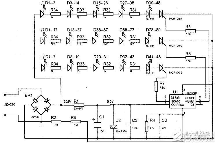
The working principle of the circuit begins with the AC 220V power supply being rectified and then passed through resistor R1 and capacitor C1 for voltage reduction and filtering, resulting in a stable +5V DC supply to the microcontroller U1 (12C508A). At the same time, the unregulated power is directly supplied to the anode of the red, green, and blue LEDs. When the 12C508A is powered on, it sequentially outputs a 0–0.76V pulse signal from its 5th, 6th, and 7th pins, which triggers the corresponding thyristors to conduct, causing the connected LED strings to illuminate in sequence. The 4th pin of U1 is connected to resistor R4 and capacitor C3 to adjust the timing of the LED switching (by changing the values of R4 and C3, you can modify the duration each LED string remains lit). Resistors R2 and R3 are used to ensure proper startup of the 12C508A when power is applied. The entire cycle lasts approximately 2 minutes, creating a smooth and continuous color transition effect.
The full LED string consists of 12 strips, each measuring 15mm in width and 465mm in length, totaling 528 LEDs. The red, green, and blue LEDs are arranged alternately across the strips. Specifically, there are 80 red LED strings, each containing 20 series-connected 1.2kΩ/1W current-limiting resistors, providing a current of 13.7mA. For green and blue LEDs, there are 48 each, with 12 strings per color, each using a single 1Ω/1W resistor to limit current to 15mA. These LEDs are arranged in a hybrid cross pattern across 44 PCB boards, ensuring even distribution of light and color output.
Common faults include no light after powering on. This is often due to an open circuit in R2, R3, or R1, or damage to the 12C508A chip. If one particular color remains lit continuously, it may indicate a faulty thyristor (MCR100-6) that controls that specific LED group. Another frequent issue is aging or burnout in an LED string, which can cause a complete loss of current flow in that section. To identify the faulty LED, a 3.0V power supply and a 20Ω resistor can be used to test each LED in sequence. Once identified, simply replace the non-working LED to restore normal operation.
When performing repairs, always make sure to disconnect the power supply before soldering or testing components. Safety should always be a priority. A detailed circuit diagram is provided for reference, as shown in the image below.
Wire Processing Machines,Cutting Sheet Metal Machine,Wire Stipper Machine,Wire Cutting Machine
Kunshan Bolun Automation Equipment Co., Ltd , https://www.bolunmachinery.com