Because different types of electronic products need to use different chargers, it is necessary to find a suitable socket and straighten the wiring when charging. The author uses the principle of electromagnetic induction to design a smart wireless charger. The wireless charger has automatic inductive charging and intelligent power-off after full charge. It is not only suitable for electronic products with different charging voltages and capacities, but also capable of simultaneously charging multiple different electronic products. The design adopts the design idea of ​​intelligent wireless charging, which has the advantages of convenient use and wide application, and has high promotion and application value.
1. System Overview
1.1 Current charging mode
Today, with the rapid development of electronic technology, the number of mobile phone users worldwide has reached 3.3 billion. Together with other peripheral electronic products such as MP3 and MP4, on average, less than two people have a portable electronic product that needs to be charged. At present, data line plug-in charging is commonly used. This type of charging method has a bad touch phenomenon when the data line interface is used for a long time, and the individual chargers are not widely adapted, because different types of electronic products need to use different ones. The charger, when looking for a suitable socket and smoothing the wiring, can be said to be time-consuming and laborious; charging various portable electronic products is a headache. In order to improve the above phenomenon, it is necessary to develop a smart wireless charger.
1.2 Introduction and advantages of the work
The intelligent wireless charger utilizes the principle of electromagnetic induction, which is a non-contact charging system, which no longer transmits power through a wire (charging line), but is charged by wireless transmission. There is no physical interface used for charging. Compared with the general charger, it avoids the trouble of plugging or unplugging the battery. It has the working principle of the general charger. The work uses one (charger) to charge multiple (inductive load) and intelligently charge. Design idea; when the wireless charger charges the load, the indicator light will be converted from green light to colorful light, and the mobile phone also correctly displays the charging status and intelligently completes the charging process (the experimental product is a mobile phone). The charger can charge multiple loads at the same time, can automatically sense whether there is load charging, achieve automatic charging, automatically power off 10 seconds after full charge, to achieve intelligent; thus greatly facilitating users. The smart wireless charger is very convenient to use, and a charger can meet the needs of a family. It has the advantages of high promotion and application value, low cost (similar to the price of a general charger), and many other large companies in the world (such as Sony). , Intel, Apple, Philips, etc.) is also in the hot research; smart wireless charging will be the development direction to replace the physical plug, will certainly be welcomed and valued by people.
Based on the above ideas, make full use of the knowledge of electronic technology learned, and be carefully guided by the teacher. Design and manufacture smart wireless chargers with the following advantages:
(1) low cost
The circuit is composed of a pulse generating part, a power amplifying part, a filtering part, a comparing part and a transmitting and receiving part, each part is composed of only a few small components, and is simple to manufacture.
(2) one-to-many charging
One charger can charge multiple loads, and one family can purchase one charger to meet the needs of the whole family. As the load increases, the work efficiency will also increase, thus saving power and reducing unnecessary expenses. .
(3) Convenience
Compared with the general charger, it reduces the trouble of plugging and unplugging, and also avoids the phenomenon that the interface is not suitable, the contact is bad, and the elderly can also be conveniently used.
(4) Intelligent
As long as the inductive load is placed on the charger, it can be automatically inductively charged. Through information feedback, when the inductive load is fully charged, the power is automatically turned off to realize the intelligent charging process.
2. Overview of working principle
2.1 System Module
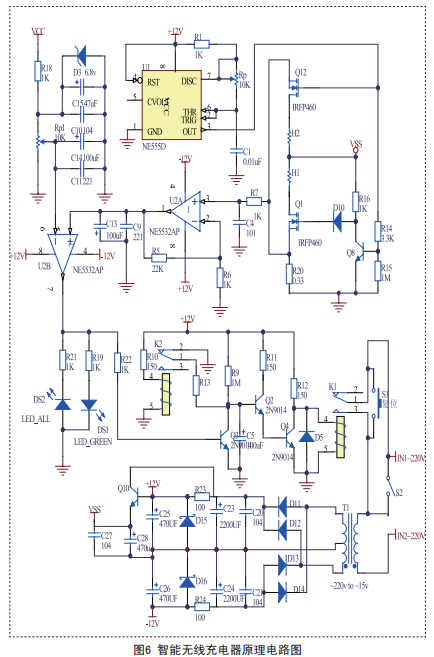
The wireless charger utilizes the principle of electromagnetic induction. A 36.7K pulse frequency is generated by the NE555D chip (because the debug is at the 36.7K frequency, the efficiency is the highest), the IRFP460 power is amplified, so that the transmitting coil generates a magnetic field, and when the receiving coil is close, an induced current is generated, after full-wave rectification and Voltage regulation, get the charging voltage and current required by the load (mobile phone). The current of the transmitting coil will increase with the increase of the inductive load. The load voltage of 0.33 ohm is amplified by 23 times by the operational amplifier, and then the voltage U1 is compared with the reference source Uo after 1N4148 rectification and filtering. When charging, U1 is larger than Uo colorful lights, indicating that charging is in progress; when empty load or full charge, U1 is less than Uo, green light is on, if there is no inductive load after 10 seconds, it will automatically power off; press reset button to restart the charger start up. The specific circuit analysis is as follows:
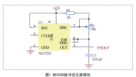
2.1.1 NE555D pulse generator module
As shown in Fig. 1, according to T = (R1 + Rp) C1, f = 1 / T, the adjustment of Rp causes the NE555D to output a pulse frequency of 36.7 kHz.
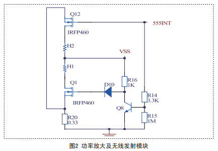
2.1.2 Power amplification and wireless transmitter module
A 36.7KHZ pulse power generated by the NE555D is amplified and transmitted through the transmitting coil. When the pulse is high, Q12 gate is high level, Q12 is on. At this time, Q8 is saturated, Uceq voltage is only 0.67V, Q1 gate voltage is 0 after D10-4148, Q1 is cut off. When the pulse is low, Q8 and Q12 are turned off at the same time, and the current is directly turned on by R16 D10 Q1 and Q1. Throughout the process, both Q1 and Q12 work in an open and closed manner. The circuit is shown in Figure 2:
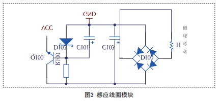
2.1.3 Induction coil module
As shown in Fig. 3, when the induction coil is close to the transmitting coil, an induced current is generated. After full-wave rectification, according to the charging voltage of different electronic products, different Zener diodes can be selected, and then the current is amplified by the transistor Q100. Supply different electronic products for charging.
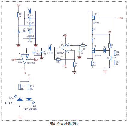
2.1.4 Charging detection module
When there is an inductive load, the voltage on the R20 (0.33 ohm) resistor will increase. After the amplifier U2A amplifies A=1+R5/R6=23 times, the voltage changes obviously, and after 1N4148 rectification and filtering, the voltage U1 is obtained. Reference source U. Compare, U1>U at this time. The op amp output Ui is at a high level, and the colorful lights are blinking; when the inductive load is fully charged (or no load is sensed), U1 < U at this time. The op amp output Ui is low and the green light is on.
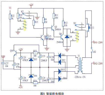
2.1.5 Intelligent power off module
(1) When the switch S2 is turned off, the whole charger is in the smart charging process. When the charger is started, relay K1 is closed and K2 is off. When there is an inductive load, the colorful lights flash, Ui is high, at this time Q5 is saturated, the voltage Uceq is 0.67V, lower than the sum of the turn-on voltages of Q2+Q4 (1.34V), Q2 and Q4 constitute Darlington At the same time, the relay K1 is closed; when the inductive load is fully charged (or no inductive load), the green light is on, that is, Ui is low, and at this time, Q3 is cut off, and capacitors C5 and R9 constitute an RC charging circuit, when the capacitor is charged. When the voltage reaches the turn-on voltage of Q2 and Q4, Q2 turns on and saturates Q4. At this time, the relay operating voltage is only 0.67V, the relay is turned off, and the whole circuit is completely powered off. After the power is turned off, the relay K2 is closed, and at this time, C5 and R13 constitute an RC discharge circuit, and the C5 is quickly discharged. When you tap the reset switch, the charger restarts. When the inductive load is fully charged (or no inductive load), capacitor C5 is charged and its voltage is Ut.
Obtained by the formula Ut=12*(1-et/R9C5): t=-R9C5ln(1-Ut/12)
Where C5=100UF, R9=1MΩ, Ut=1.34V,
Calculated power outage time: t=10S
A 10 second automatic power off is achieved. As long as there is an inductive load within 10 seconds of the green light, Ui is high, Q3 is saturated, and capacitor C5 is discharged. Intelligent power-off is achieved throughout the charging process.
(2) When S2 is closed, the entire charging circuit is in a manual power-off process.
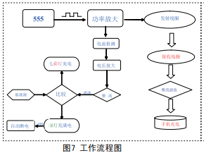
2.1.6 Flowchart
The specific workflow is shown in Figure 7:
2.2 System Implementation
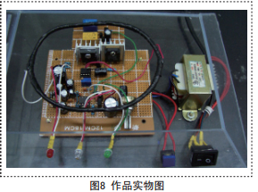
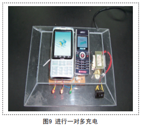
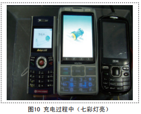
The physical map of the system is shown in Figure 8, Figure 9, and Figure 10.
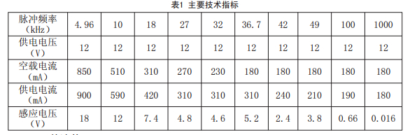
3. Main technical indicators
The main technical indicators of the work are shown in Table 1.
4. Component list
The main components used in this system are listed in Table 2:
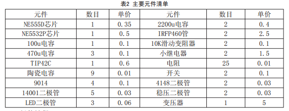
According to statistics:
The total price of components is $=17.18 (yuan).
5. Works expansion
Through research, we find that the application field of wireless electromagnetic induction charging is very wide. In addition to charging for the most basic mobile phones, MP3, MP4, notebook computers, digital cameras and other portable devices, it can also be applied in medical and industrial fields, especially for those. A completely sealed device has a more important meaning; if the transmitting coil is placed inside the mouse pad, the mouse can be wirelessly powered. In fact, in addition to inductive charging, you can also achieve the functions of mosquito repellent and mouse by changing the pulse frequency.
6. Conclusion
This design truly applies the professional knowledge learned in the current electronic course to practice. Due to the reasonable design of the work structure, the circuit function is better, the performance is excellent and stable, and the various indicators of the expected design requirements are well achieved.
Attachment: List of equipment
Function signal generator
Digital multimeter
Analog multimeter
Distortion measuring instrument
Digital scope
Power Supply
UHF millivoltmeter
references
[1] Xu Shoushi. Signal and system [M]. Hefei: China University of Science and Technology Press, 2003.
[2] Zhang Guifen. Electronic Technology Foundation [M]. Beijing: People's Posts and Telecommunications Press, 2005.
[3] Zhao Shujie, Zhao Jianxun. Signal detection and estimation theory [M]. Beijing: Tsinghua University Press, 2005.
About the Author:
Luo Tao (1981-), male, assistant professor of Guangdong Institute of Mechanical and Electrical Technology, the main research direction: electronics and communications.
Traffic Safety Sign,Prohibition Traffic Sign,Led Traffic Sign Board,Led Traffic Sign Light
Jiangsu Bosiwei Optoelectronics Group Co.,ltd , https://www.bswledled.com