introduction
At present, portable electronic devices such as mobile phones, MP3s, and notebook computers are mainly charged by a conventional charging method in which one end is connected to an AC power source and the other end is connected to a portable electronic device charging battery. There are many disadvantages in this way. For example, frequent plugging and unplugging can easily damage the connector, and it may also cause electric shock. Therefore, the non-contact inductive charger was born at the end of the last century. With its advantages of easy portability, low cost, and no wiring, it has quickly attracted attention from all walks of life. To achieve wireless charging, energy transmission efficiency is high, and it is easy to carry one of the research directions of charging system. The design is a charger consisting of two parts, an energy transmitting unit and an energy receiving unit, and utilizing the principle of electromagnetic induction to realize wireless transmission of electric energy.
1 hardware system design
1.1 Device Selection
The design of the wireless charging system is to transfer energy by means of coil coupling, so that the receiving unit receives enough electric energy to ensure the supply of energy of the subsequent circuit. Since the wireless power transmission voltage needs to be changed in the test according to the distance D between the energy transmitting unit and the receiving unit coupling coil, and the charging time is relatively fixed and convenient for control, the constant current charging scheme of the fixed current charging is selected in the charging mode. Selecting a variety of power-saving modes on the device selection, the power consumption is particularly low, and the MSP430 series ultra-low-power single-chip MSP430F2274 with strong anti-interference ability is used as the monitoring and control core chip of the wireless energy-passing charger. The voltage and charging time display is low. Power consumption OCM126864-9 LCD screen to improve the energy efficiency of the charging circuit.
1.2 System Block Diagram
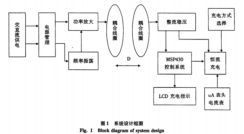
The wireless charging system mainly adopts the principle of electromagnetic induction, and energy transfer through the coil realizes energy transfer. As shown in Figure 1, when the system is working, the input terminal converts the AC mains into a DC power through the full-bridge rectifier circuit, or directly supplies the system with a 24V DC terminal. When the receiving coil is close to the transmitting coil, an induced voltage is generated in the receiving coil, and when the resonant frequency of the receiving coil loop is the same as the transmitting frequency, resonance occurs, and the voltage reaches a maximum value, which has the best energy transmission effect. The energy is coupled through two inductor coils, and the current output from the secondary coil is converted into direct current by the conversion circuit to charge the battery.
1.3 unit circuit design
1.3.1 Power Switching
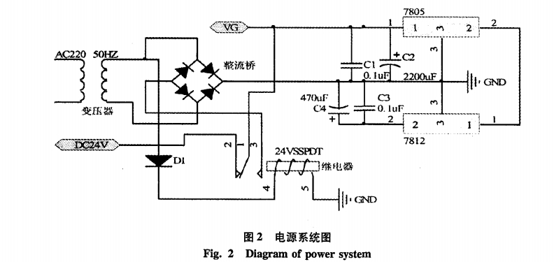
The DC input adopts single-pole double-gate relay, the AC power-on is normally open and closed, the normally-closed open realizes the AC priority, the AC power-off relay is powered off, the normally closed and closed, and the automatic switching is realized. When switching, the time is very short, C1 can provide a certain amount of power, can achieve continuous power switching, does not affect charging. See Figure 2.
1.3.2 Transmitting and receiving circuits
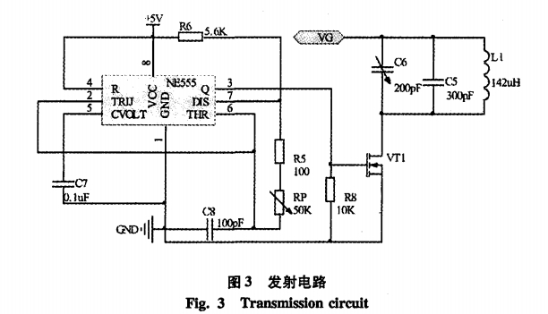
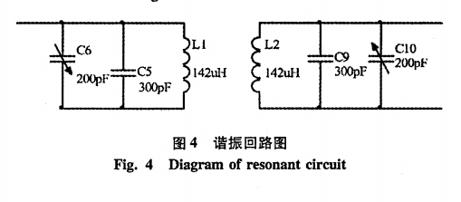
The transmitting circuit is composed of an oscillating signal generator and a resonant power amplifier, as shown in FIG. The signal generator with an oscillation frequency of about 510KHZ is used to form an excitation signal for the power amplifier circuit. The resonant power amplifier is composed of an Lc parallel resonant circuit and a switch tube IRF840. The oscillating coil is wound around the 2O circle with an enameled wire with a diameter of 0.8mm as required. The diameter is about 6.5cm, and the measured inductance is about 142uH. 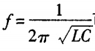 When the resonance is at 510KHZ, the capacitors c5 and c6 connected in parallel with it are about 680P. A fixed capacitor of 470pF can be used in parallel with a fixed capacitor of 200PF to adjust the resonant frequency.
The maximum current of the high-power tube TRF840 is 8A, and the internal resistance is 0.85 ohm when fully opened. The heat of the tube is large, so it is necessary to install a heat sink. When the resonant frequency of the frequency selective loop of the power amplifier is the same as the excitation signal frequency, the power amplifier resonates, and the voltage and current in the coil reach a maximum value, thereby generating the largest alternating electromagnetic field. When the receiving coil is close to the transmitting coil, an induced voltage is generated in the receiving coil, and when the resonant frequency of the receiving coil loop is the same as the transmitting frequency, resonance occurs, and the voltage reaches a maximum value. A resonant circuit as shown in FIG. 4 is constructed. In fact, both the transmitting coil loop and the receiving coil loop have the best energy transmission effect when they are in resonance.
1.3.3 Charging circuit
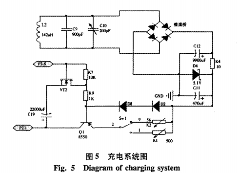
As shown in Figure 5, after the electric energy is received by the coil, the high-frequency AC voltage is full-wave rectified by the fast diode 1N4148, the capacitance of the 3300F is filtered, and then the 5.1V voltage diode is used for voltage regulation. The output DC power provides a relatively stable operation for the charger. Voltage.
because 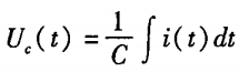 In order to accurately control the charging time, we adopt the method of constant current charging in the design to ensure that the charging current is approximately a constant I. The relationship between the above voltage and time can be expressed as:
 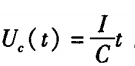 . According to the requirements of the title, the charging time should meet the fast charge less than 30s, the slow charge control in the 100 to 140S, calculate the fast charge, slow charge required current fast I1 slow I2: respectively:
The turn-on voltages of the diodes D1 and D2 in Fig. 5 are substantially constant, so they can be used as a voltage reference and are about 1.4 V. The voltage relationship is:
It can be seen that in the constant current charging circuit, the charging current is determined only by the resistors R1, R2. In the calculation, it is agreed that U=0.7 charging current Ic (triode collector current) Ie, and the required resistors R1 and R2 for fast charging and slow charging are calculated as:
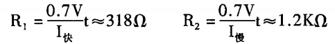
An adjustable resistor is used in the design to adjust the charging current.
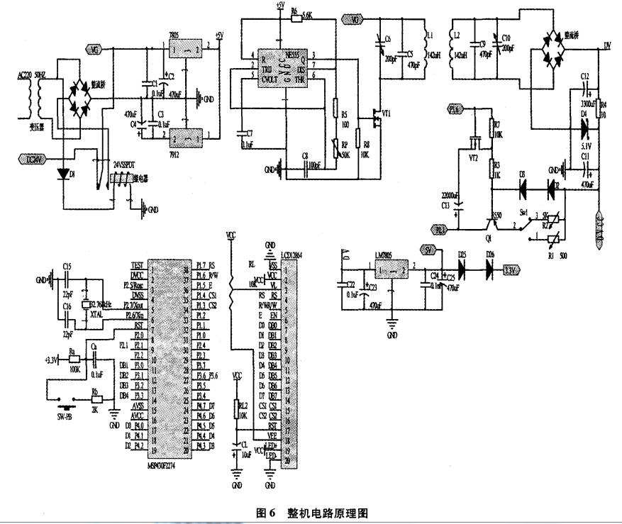
1 .3. 4 whole circuit schematic
2 software design
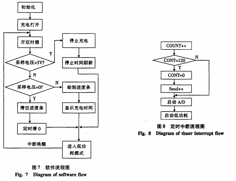
The main task of software design is to monitor the charging process and control the charging circuit. The specific method is: using the AD converter of the MSP430 single-chip microcomputer to detect the voltage on the rechargeable battery in real time, and send a control signal to the specified voltage to break the charging circuit. Based on the MSP430's high speed, high-precision AD converter, and feature-rich timers, we designed the charging progress bar, real-time charging voltage display, and charging time display on the LCD. The drawing of the progress bar needs to qualitatively reflect the real-time voltage. The method we use is to calculate the coordinates based on the voltage value, and call the drawn straight line function designed by ourselves to draw in real time, the effect is realistic (see Figure 7, Figure 8).
3 function implementation
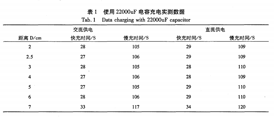
The wireless charging system is designed to use 220V / 50HZ AC power supply, 24V DC power supply, automatically switch AC and DC power supply; with fast charging and slow charging function, when the distance D> 2cm, fast charging time <30s, when the distance D> 2cm When, the slow charge time is <120s. When the system is full, it will display and automatically turn off the charging. As shown in Table 1.
4 Conclusion
Charging efficiency is a problem that has to be considered. The design system can be appropriately modified in the energy transmission part of the transmitting and receiving circuit to obtain higher efficiency and longer distance; the charging device detecting circuit can also be designed, and the energy transmitting part is in a sleep state when there is no energy receiving circuit, when When the energy receiving circuit is close to the transmitting portion, the transmitting circuit is activated to start charging. The design system meets the design requirements, has the advantages of wireless charging, convenient carrying, low cost, no wiring, and has wide application prospects.
Super Bright & Power Saving: 30W handheld Led Work Light, 1500 Lumen, replace 200W traditional halogen bulb by 30W COB LED and save 80% on electricity bill of lighting
LED Work Lights Portable & Flexibility: Because the rechargeable flood light is cordless. with a 180 degree adjustable lamp stand. So you can put it in anywhere just you like. led portable Work Light hanging on truck or hand held. Even on the ground, in the basement, garage or garden at night
3 Modes & Waterproof: Press the switch on button turn on the work light rechargeable: High, Low, Strobe Brightness Mode. IP65 Waterproof rating, ensure the Rechargeable Led Work Light works fine in rainy days
LED Work Light Rechargeable & Battery Powered: Powered by 2 18650 lithium-ion rechargeable batteries(included) or 4 AA batteries(not included), equipped a USB cable allows for quick and convenient charging. Also Serve as a convenient power bank for charging your phone and other devices in emergency
Portable Flood Light Widely Used: Camping, Hiking, Fishing, Barbecue, Car Repairing, Truck, Workshop, Construction Site, Job Site Lighting, Exploring and more Outdoor Activities
Work Light
Led Work Light,Rechargeable Work Light ,Work Lamp,Rechargeable Led Work Light
Ningbo Wason Lighting Technology Co.,Ltd , https://www.wasonlight.com